Airbus A320-214
I would say that A320 represents the main method for traveling through the air and that is why I chose it as my artefact. Even before I started, I prepared all blueprints and materials, which could be useful later. I built 3 plains and textured them as blueprints. This helps me with modelling a lot because I am familiar with blueprints, I understand them, I can also create them.
I started with a cylinder that was divided to 13 vertical segments. I was editing the width, height and position of every ring step by step. At the start and end of the aircraft the centre of imaginary circles is moving on vertical axis. On the end the circle almost, merges with the top of the aircraft. Here I haven’t used lofting intentionally. It wasn’t necessary to use it now and the work with cylinder was much easier.
The next part were wings. It’s necessary to say, that I am now using the symmetry function. This was helpful because I didn’t need to copy and duplicate everything twice. I have just found the centre of aircraft, here I have created imaginary mirror, and magic happens. Back to the wings. I thought if it is easier to take a simple cube and edit it to the shape of wings. As I don’t need much of a low-poly model, this will not be a good way. I need the model to be as real as it can be without texturing. So, I chose a different technique. I’ve created an outline of the wing and then extruded that. I also thought about animating the model in the future, so I made holes for flaps, which can be animated. Now I have something which resembles a wing but it’s straight. So, I have added one more vertical segment and converted it to the editable poly. Even on the wings aerodynamic elements need to be preserved, so I have pull out the middle edge and I made it smoother and to make the edge not so sharp. Then I have started to work on thickness of wing. As farther it is from the bode, as narrower it is. I created the smaller wings on the end of aircraft same way. Rudder is created from cube. Although there were no difficulties, I had to rework it later, because of the movable rudder.
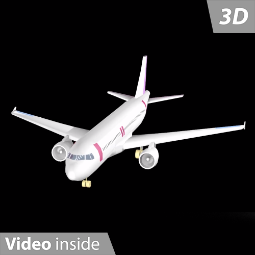
First part is done. The second part is to create flaps, engines and finally gear. Flaps were created as wings with outlines and extrude. But I needed to change their angle, so it will fit to wing well. Flaps are very vulnerable parts, so it was needed to give them support. There are 3 canoe-shaped objects from the bottom of the wing – “aircraft fairing”, which take this role on them. I created flaps on the back wings the same way, there isn’t support needed. In the picture is clearly shown the problem with rudder. Theoretically it would be enough for the model, but as I mentioned, I want to work with model further, so I think this feature doesn’t hurt the model in any way.
The next step was the engines. Here I’ve used one of aircraft fairing because the clutch that holds the turbine is quite like the shape of the flap support. Engine is modelled from basic object tube. I have set relatively high number of vertical segments and 2 segments on the cap as I will need the aerodynamic shape on engines as well. I reshaped the side shape of engine as well as I did it on the main body of aircraft. Probably the most demanding part of the whole model are the blades in the turbine. In Maya I would solve it with python. As I haven’t found anything like that in MAX, so I had to do it manually. I counted blades on the original picture, created 2 against each other, duplicated them, and then turned them over a few degrees. Since each blade had a reference in each other, I could edit and adjust them easily.
Then I needed to create gear. With couple of cylinders I’ve created pneumatics, construction which holds the gear and lights as well. Here I have used the required lofting specifically for the gear cabling. Gear is another very vulnerable part of the plane, so I think it deserves the model to see the shortcomings that Airbus left uncovered. For front gear I have created a hole into body. When the gear is down, part of body is opened. Same it is on the rear gear, there I’ve solved it with individual extruded spline.
If I do that model for a game engine, I would leave it like that and I will solve another feature with alfa channel on the textures. But I needed to provide my knowledge of modelling, so I decided to model windows and doors. The procedure was as follows. I duplicated the body, which I scaled down a little, then created objects that use the Boolean function to create a hole in the desired shape, which I also duplicated. I doubled the body again. I made a hole in one and made an intersection with the other. So, we have a door that can be animated, that fits perfectly. At the very end I worked on the windows. I simply created a shape (classic curve, then extrude), I used the blueprints to copy them and then I made holes in the body and doors. The last thing were the main windows for the pilots, which I created with the other shapes as well as the passenger windows. The NURBS technique was used within the windows for the pilots. Glass has a lower opacity to simply simulate a window.
Since I create sceneries for Prepar3D, I know what I can and can’t use. The rather outdated game engine does not support the NURBS technique well, so I tried to save this technique and used polygon editing instead. Any colour parts on the final model could animate in the future. Previously I worked in Cinema4D, so transfer to 3Ds MAX wasn’t that hard. I knew lofting. I knew how to edit mesh. In compare with Cinema4D I don’t really like that changing of views in MAX (this has better solution in Maya), but I found useful keys “QWER”. The interface of 3Ds MAX is fine, friendly, easy to use.